Daunt
MLG Pro
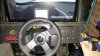
I know a lot of people have wanted their own custom button box (Besides Noel - if you're Noel, read no further)... well I am putting this guide together to show you how simple it is.
I don't have any electrical experience, nor soldering experience. So that should tell you it's very doable... but there's not very much to it at all, really.
What you need:
Step 1 Disassembly
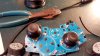
Disassemble the controller. You'll end up with a naked board, but you'll see where the button, when pressed, makes contact. I'm not sure what the technical term is, but the area that gets pressed has 2 separate connections. When the button is pressed, it connects those two separate areas, thus creating a circuit.
That's all that happens. It's real simple. So all you're doing is changing where and how those two spots connect. Before it was from the bottom of the button press, now it's a switch that completes the circuit.
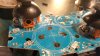
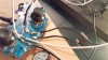
In the above picture, you can see the Dpad's naked assembly. You might have to view the picture large, but you can see that each of the four spots where contact is made, has two distinct hemispheres. It's a very fine divider, which is why the soldering was so tricky.
So with it disassembled, I plugged it into the PC and used a program called xpadder. It's a great program that allows you to custom map anything to xbox controller's buttons (so even for a game that doesn't allow an xbox controller, I can map Ctrl+P or Alt+F4 to the A button or whatever.
More importantly - I can use the program to easily see that a button is being activated. So not having done anything but disassemble the outer case, I plugged it back into my PC and tested the buttons.
Basically though, if you took a wire and connected the two sides, you complete the circuit and you would see, as I did through my testing program, the button is activated.
Step 2 Wiring Switches and Buttons
As I said before, the important switches, based on what I'm using them for, are momentary button presses and momentary on-off-on toggle switches. Momentary buttons function exactly the same as the buttons on the xbox controller itself did, it completes the circuit (and thus activates the button) only when the button is depressed. The other, the momentary on-off-on switch is a switch that is off in the center and to activate, you can flip up or down, which completes the circuit only while the switch is up or down.
For these images, I just wired the buttons. You'll see the back of the button has two separate screws for the wire to attach to. I connected 1 black and 1 white wire to each button (one on top one on bottom, doesn't matter which), taped it up and viola, all done with that part. Repeated with rest of buttons and switches. The switch, since it technically has two buttons, as two screws on top/bottom then only one in the center. The two buttons can share the one center wire.
Each time I wired up the buttons/switches and taped them, I doublechecked with Xpadder that they still functioned properly so when a problem occurs later on, I know that this wasn't the issue. So I'd plug in the controller, put the two wires on each side of the spot, then press to confirm that the button worked. Testing as much as possible is always a good thing and you'll thank yourself later.
Step 3 Soldering
So on to the part that made me the most nervous. I did plenty of testing on soldering before actually doing it on the board. Trying to learn how the solder rosin behaved when it was a liquid metal and how the wire would remain when solidified.
Again, I had plenty of extra wire so I spend at least 20 minutes fooling around trying to see the best way to solder. This soldering job is made tougher because of how small those contact points are. The rosin is also conductive, so in other words, each solder has to be separate. Putting one big blob solder atop the contact would simply complete the circuit without the button, rendering it "always on".
So after plenty of practice and reading about the best techniques to solder onto a circuit board, I delved in still nervously. The best way to go about it that I read and practiced, was to melt some of the rosin directly onto the iron, then let it solidify. Then you'd have what you'd need ready on the iron already. I heated up the board slightly... not too much as heat will damage the board, but once done, I held the wire in place while applying the heat to the wire. The heat would re-melt the rosin, then it was just a matter of ensuring the rosin did not melt and solidify into a point where it would touch the other side.
It took quite a bit of heat, because if it wasn't hot enough the rosin would solidify but not adhere to the board. Thankfully though it worked. After each button was soldering, I'd go over and test each one to ensure I didn't screw anything up.
At one point I had a little rosin get in between the two sides, which, when I tested, showed the buttons as being continuously on. I carefully scraped the one in question with a screwdriver head to clear out the divider. There probably is a better way to handle this, but it worked. Just be careful if you end up having to do this. There was barely any rosin there so certainly don't do it if there's a lot.
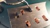
So repeat for each button. In all with the xbox controller, it was possible to get I believe 12-14 buttons mapped. I didn't need a whole lot, and I didn't want to mess with the bumpers, triggers or thumbsticks.
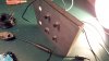
It may look like an absolute mess, but it works. Each wire is connected to 1 of 2 sides. Success!
I don't have any electrical experience, nor soldering experience. So that should tell you it's very doable... but there's not very much to it at all, really.
What you need:
- Wired xbox controller - I used a 360 controller, I'm sure you could use other ones.
- Wire - I grabbed 2x 10 ft wire, 16 gauge. One black one white. The amount is more than enough. The switches indicated they needed something that could handle 10 amps, so I went with the smallest gauge that could handle that. (The higher the gauge, the smaller the wire)
- Soldering iron and solder - One that is suited for fine work, especially circuit boards, is ideal. Unfortunately I didn't have one, so you'll see my soldering work is a bit messy.
- Switches and buttons - There's all different kinds but I settled for two real important ones (to me)... 4x momentary on buttons, and 2x momentary on-off-on toggle switches.
- A program to test - I used xpadder, which I'll talk about later.
Step 1 Disassembly
Disassemble the controller. You'll end up with a naked board, but you'll see where the button, when pressed, makes contact. I'm not sure what the technical term is, but the area that gets pressed has 2 separate connections. When the button is pressed, it connects those two separate areas, thus creating a circuit.
That's all that happens. It's real simple. So all you're doing is changing where and how those two spots connect. Before it was from the bottom of the button press, now it's a switch that completes the circuit.
In the above picture, you can see the Dpad's naked assembly. You might have to view the picture large, but you can see that each of the four spots where contact is made, has two distinct hemispheres. It's a very fine divider, which is why the soldering was so tricky.
So with it disassembled, I plugged it into the PC and used a program called xpadder. It's a great program that allows you to custom map anything to xbox controller's buttons (so even for a game that doesn't allow an xbox controller, I can map Ctrl+P or Alt+F4 to the A button or whatever.
More importantly - I can use the program to easily see that a button is being activated. So not having done anything but disassemble the outer case, I plugged it back into my PC and tested the buttons.
Basically though, if you took a wire and connected the two sides, you complete the circuit and you would see, as I did through my testing program, the button is activated.
Step 2 Wiring Switches and Buttons
As I said before, the important switches, based on what I'm using them for, are momentary button presses and momentary on-off-on toggle switches. Momentary buttons function exactly the same as the buttons on the xbox controller itself did, it completes the circuit (and thus activates the button) only when the button is depressed. The other, the momentary on-off-on switch is a switch that is off in the center and to activate, you can flip up or down, which completes the circuit only while the switch is up or down.
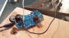
For these images, I just wired the buttons. You'll see the back of the button has two separate screws for the wire to attach to. I connected 1 black and 1 white wire to each button (one on top one on bottom, doesn't matter which), taped it up and viola, all done with that part. Repeated with rest of buttons and switches. The switch, since it technically has two buttons, as two screws on top/bottom then only one in the center. The two buttons can share the one center wire.
Each time I wired up the buttons/switches and taped them, I doublechecked with Xpadder that they still functioned properly so when a problem occurs later on, I know that this wasn't the issue. So I'd plug in the controller, put the two wires on each side of the spot, then press to confirm that the button worked. Testing as much as possible is always a good thing and you'll thank yourself later.
Step 3 Soldering
So on to the part that made me the most nervous. I did plenty of testing on soldering before actually doing it on the board. Trying to learn how the solder rosin behaved when it was a liquid metal and how the wire would remain when solidified.
Again, I had plenty of extra wire so I spend at least 20 minutes fooling around trying to see the best way to solder. This soldering job is made tougher because of how small those contact points are. The rosin is also conductive, so in other words, each solder has to be separate. Putting one big blob solder atop the contact would simply complete the circuit without the button, rendering it "always on".
So after plenty of practice and reading about the best techniques to solder onto a circuit board, I delved in still nervously. The best way to go about it that I read and practiced, was to melt some of the rosin directly onto the iron, then let it solidify. Then you'd have what you'd need ready on the iron already. I heated up the board slightly... not too much as heat will damage the board, but once done, I held the wire in place while applying the heat to the wire. The heat would re-melt the rosin, then it was just a matter of ensuring the rosin did not melt and solidify into a point where it would touch the other side.
It took quite a bit of heat, because if it wasn't hot enough the rosin would solidify but not adhere to the board. Thankfully though it worked. After each button was soldering, I'd go over and test each one to ensure I didn't screw anything up.
At one point I had a little rosin get in between the two sides, which, when I tested, showed the buttons as being continuously on. I carefully scraped the one in question with a screwdriver head to clear out the divider. There probably is a better way to handle this, but it worked. Just be careful if you end up having to do this. There was barely any rosin there so certainly don't do it if there's a lot.
So repeat for each button. In all with the xbox controller, it was possible to get I believe 12-14 buttons mapped. I didn't need a whole lot, and I didn't want to mess with the bumpers, triggers or thumbsticks.
It may look like an absolute mess, but it works. Each wire is connected to 1 of 2 sides. Success!